Compute raster splatting
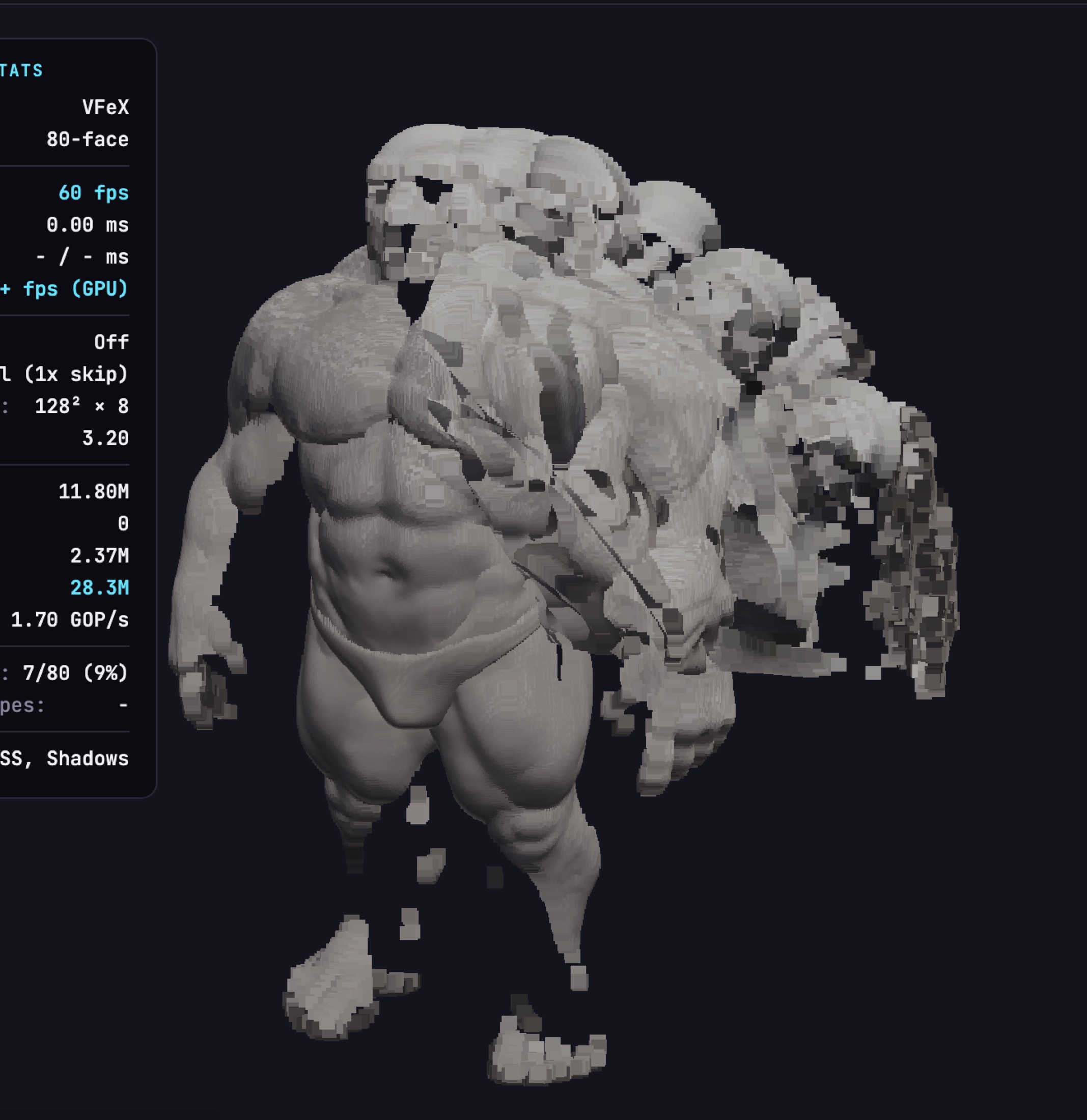
Projects VFE texels into screen space. Cost follows atlas resolution and coverage gaps require splatting and hole fill.
Independent experimental research · WebGPU · March 2026
A meshless geometry representation, three real-time rendering architectures and a browser studio built to test them.
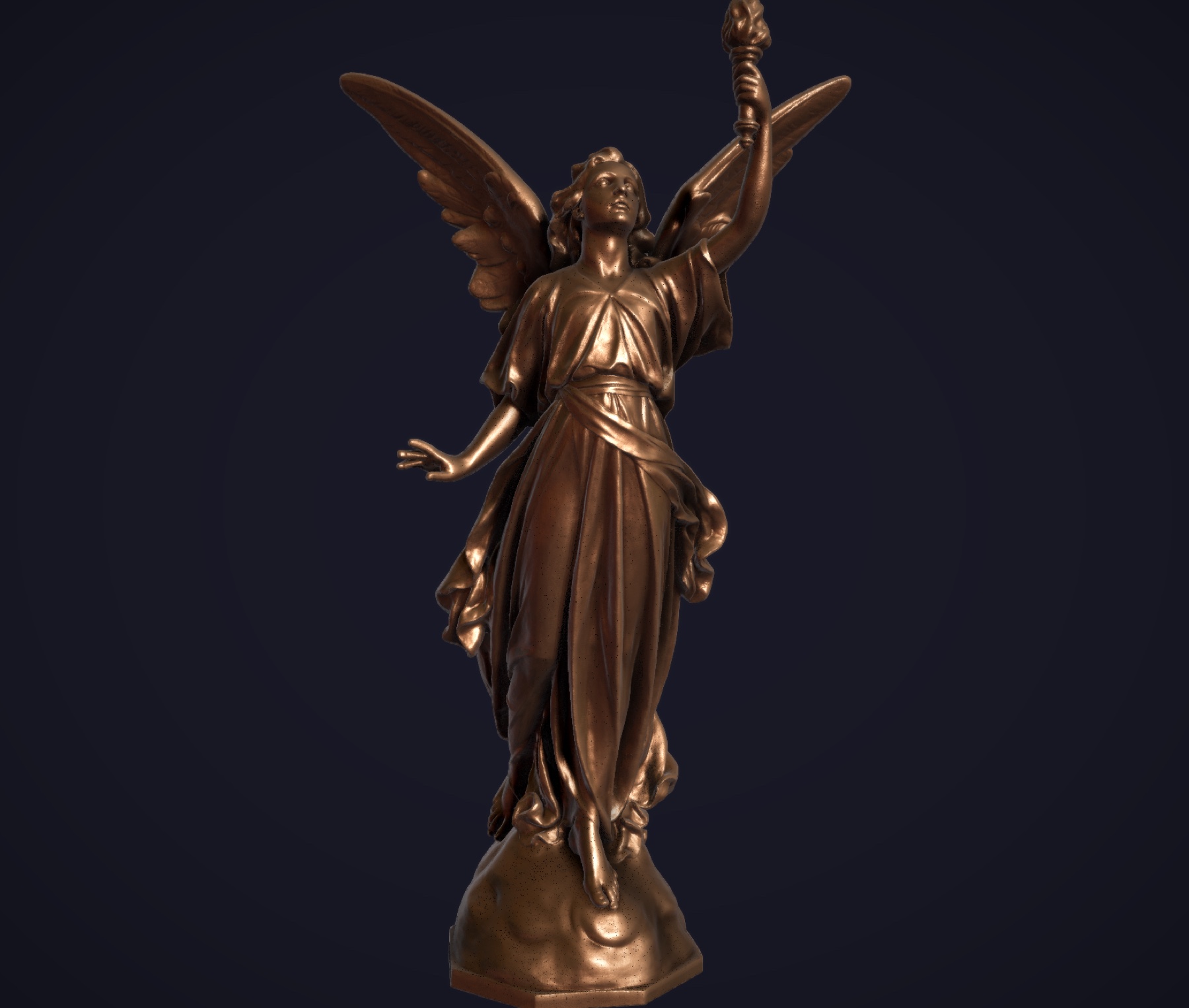
01 · The question
Polygon assets carry vertices, indices, UVs, topology and level-of-detail structures. For browser review, that can add weight and expose the original geometry.
VFE surrounds an object with a convex envelope and records inward directional depth fields from each face.
Each texel stores surface normal, normalized penetration depth and thickness. The representation is deliberately not bijective: the source topology cannot be reconstructed from the delivered file. The experiment tests whether that trade can still produce useful real-time images.
02 · One format, three renderers
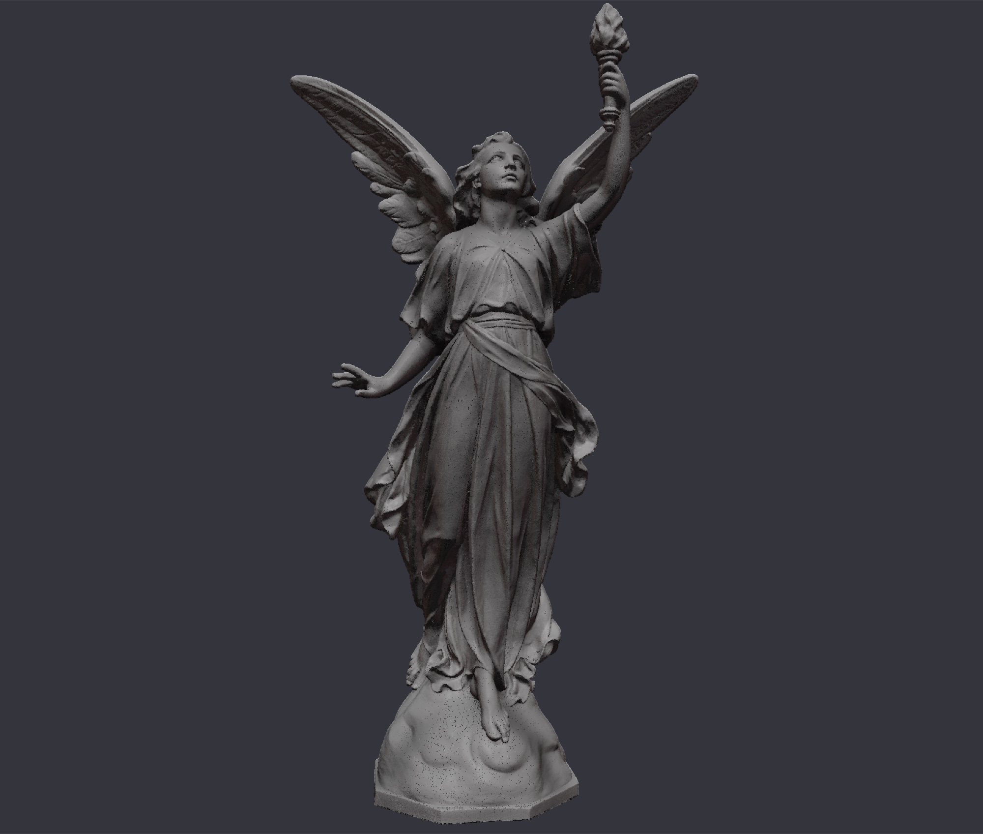
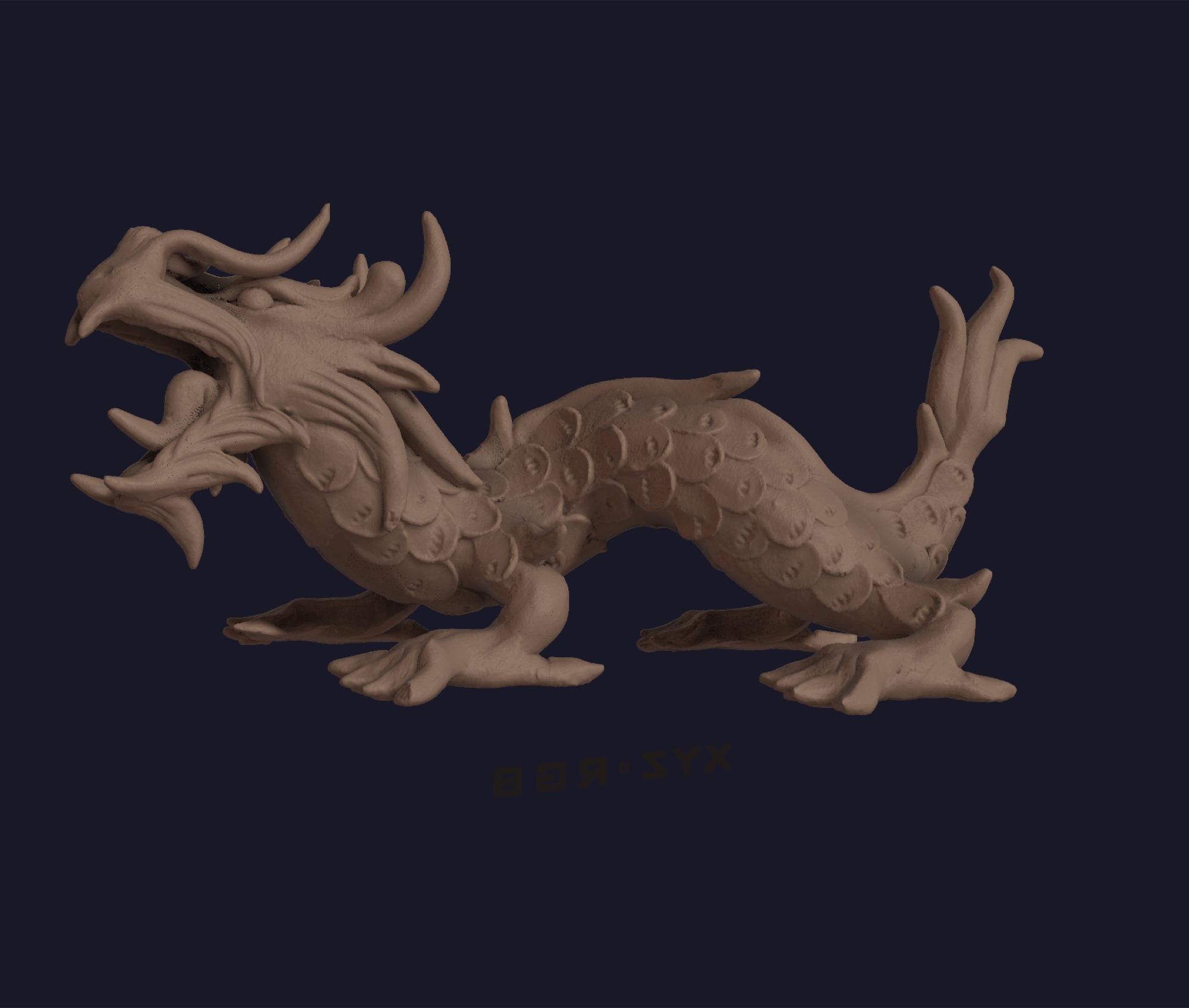
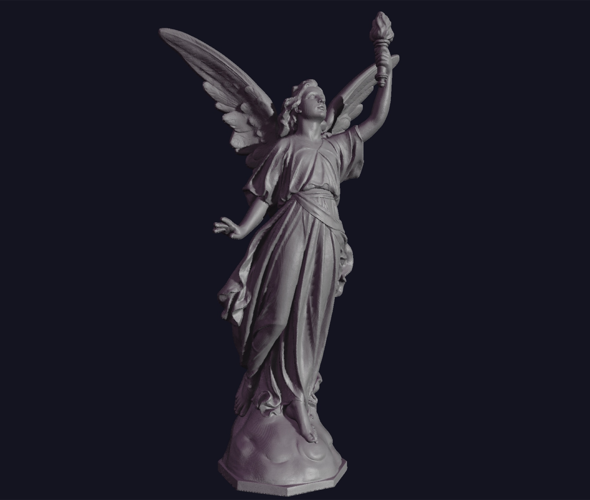
All three paths consume the same atlas and support PBR lighting, shadows and multi-envelope objects.
Projects VFE texels into screen space. Cost follows atlas resolution and coverage gaps require splatting and hole fill.
Casts from screen pixels into the envelope. Cost follows screen resolution and the result supports native temporal anti-aliasing.
Uses the GPU rasterizer for envelope coverage. Correct, but less natural for multi-envelope composition.
The prototype was built to find the trade-offs, not to hide them.
03 · Observed results
Measurements are from the documented test setup on an M1 Max and should be read as project observations, not general benchmarks.
| Path | Observed output | Main trade-off |
|---|---|---|
| VPR | About 120 fps | Atlas-bound; gaps below useful resolution |
| Pixel Triggers | About 90 fps at 1080p | More ALU work; stronger image quality |
| Hybrid | About 100 fps | No coverage gaps; weaker multi-envelope fit |
| Conversion | About 800 ms at 512px dodecahedron | Hardware and model dependent |
| 10M polygon scan | 4.2 MB compressed .vfe | Lossy, non-invertible representation |
04 · What was built
RenderClay makes the representation inspectable instead of leaving it as a shader demo.
BVH construction, chunked processing for multi-million triangle meshes and depth-based result merging.
A 64-byte header followed by sparse 28-byte surface records, with multiple envelope shapes and optional second-layer geometry.
Loading, rendering, lighting, shadow control and visual comparison in a functioning WebGPU workspace.
Independent exploratory research by Hamza Trabelsi. Built in WebGPU with WGSL and JavaScript, without external rendering libraries.
05 · Representation in detail
The envelope is a coordinate system around the object. Each face owns a directional field aimed inward at the source surface.
For each occupied texel, VFE stores an octahedrally encoded normal, normalized penetration depth and local thickness. The face index and texel coordinate provide the ray origin and direction needed to reconstruct the point.
This changes the unit of rendering. A conventional mesh asks the GPU to transform vertices and rasterize triangles whose count follows the source asset. VFE asks the renderer to process an atlas whose dimensions are chosen at conversion time. A ten-million-triangle scan and a much smaller source mesh can therefore share the same runtime budget once encoded at the same resolution.
The trade is deliberate. Fine topology, thin features and sub-texel detail can be lost. The source mesh cannot be reconstructed exactly because multiple meshes can produce the same directional field. The format is useful when predictable browser cost, compact delivery and resistance to source-asset extraction matter more than editability.
The first hit gives the visible surface. A second depth or thickness value preserves another layer along the same ray, improving shells, folds and partially occluded structure without turning the renderer into an unbounded ray marcher.
A fixed 64-byte header records the envelope, face resolution, atlas dimensions and sparse record count. Only occupied atlas texels follow. Each 28-byte surface record carries the information required to repopulate the GPU atlas. Typical occupancy at 512 pixels per dodecahedron face is about 10–20%, producing five-to-fifteen-times reduction compared with the dense atlas before transport compression.
VFE4 header (64 bytes)
magic · envelope type · face resolution
atlas width / height · sparse record count

surface record (28 bytes)
layer + pixel index · encoded normal
normalized depth · thickness / secondary hit
06 · Conversion algorithm
The converter turns an arbitrary GLTF triangle mesh into a representation designed for repeated delivery and inspection.
Fit the source inside the selected convex envelope.
Construct and flatten a traversal hierarchy on the CPU.
One compute thread casts inward from each atlas sample.
Store closest and second-closest intersections with normals.
Read back occupied samples and write the sparse VFE4 file.
Multi-million-polygon sources are divided into triangle chunks. Each chunk receives its own BVH and GPU raycast pass. After readback, the result is merged per texel using closest-depth comparison. The winning first and second surface samples are therefore the same samples a hypothetical single pass would retain.
Chunk resources are destroyed immediately after merge. A ten-million-triangle test asset processed in seven chunks in roughly three seconds; a 512-pixel dodecahedron conversion completed in roughly 800 milliseconds on the documented M1 Max setup. These are prototype measurements, not universal performance claims.
07 · Renderer architecture
The three backends were implemented because the representation alone does not determine the best way to draw it.
Compute threads reconstruct atlas samples and project them forward. An atomic minimum resolves depth. Splatting closes gaps when atlas resolution is too low for the projected footprint. Work scales with face count and atlas resolution rather than viewport size.
One thread begins at each screen pixel, intersects the envelope faces, samples candidate atlas locations and keeps the closest valid surface. Work scales with viewport resolution. Shading occurs inline and temporal anti-aliasing fits naturally.
The fixed-function rasterizer draws the convex shell. Fragment code identifies the face, samples its directional field and reconstructs depth. Coverage is clean, but composing many independently transformed envelopes is less natural.
VPR and Pixel Triggers use compute shadow depth, PBR lighting and screen-space effects. Multi-part characters are built from separate envelopes with local transforms around a common scene center.
08 · Limits and next questions
This is experimental rendering research, not a claim that meshes should disappear.
Any directional field is limited by its sampling density. Splatting repairs coverage, not information that was never captured.
Multiple envelope faces and optional second layers improve coverage, while deeply nested geometry may still require object decomposition.
The tiled runtime atlas saves VRAM, but the shadow pass retains a non-sparse copy to preserve direct coordinate mapping.
The reported frame rates and conversion times come from one WebGPU implementation and one documented machine. Broader profiling is future work.